3D40/FLX Extruder
- Unclogging Extruder
- Replace Runout Sensor
- Nozzle Gap Calibration
Unclogging the Extruder
This page will walk you through the steps to properly clear out a clogged extruder.
Since the reason the extruder may be clogged is not yet clear, the video will provide a few options to help you clear out the clog.
Instruction
This document will outline the steps necessary to clear a clog in the heatsink tube assembly caused by the filament bulging up inside the tube. If the filament becomes clogged, neither loading nor unloading will be possible. Tube clogging can occur by either using an old filament that’s kept in the open for a longer duration or from 3rd party filaments with lower transition temperatures
Tools Required
• Unclog tool
• Brush
• Scissors
• Pliers
TIP
In order to help avoid clogging please follow the recommendations below.
1. Only use Dremel filament.
2. Always unload the filament from the printer when not in use.
3. Always wait for the extruder to cool down see thermometer icon on screen empty.
4. Store your filament in a dry environment with a desiccant bag and clip the free end of the filament to the two holes in the spool to prevent filament getting tangled or brittleness.
Please call Dremel service center for help in unclogging your extruder.
Option A) Purge Filament
1. Pre-heat the extruder, go to Tools/Pre-heat. Wait until the extruder reaches the recommended temperature for your filament then click on Purge.
Option B) Pull Filament
1. Pre-heat the extruder, go to Tools/Pre-heat. Wait until the extruder temperature reaches the recommended temperature for your filament and select Purge.
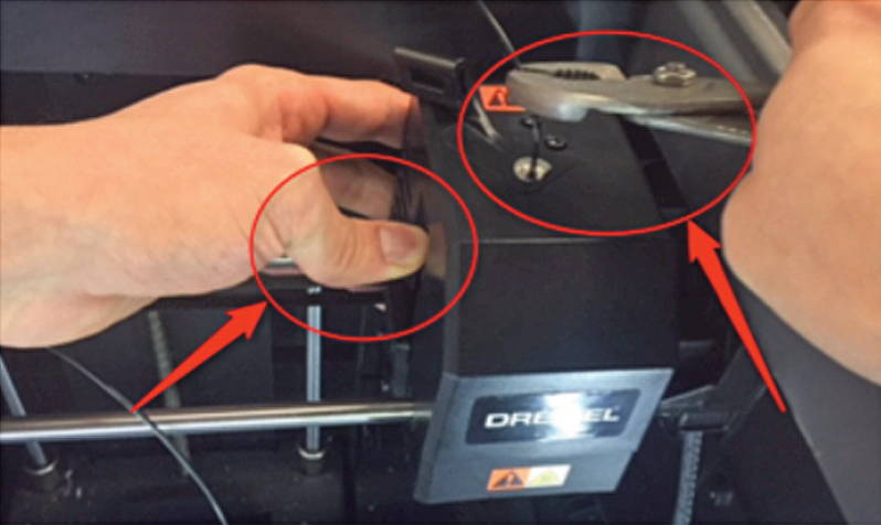
2. Grab the filament end that is available with the pliers, push on the side lever in the extruder to release tension on the filament and pull the filament at the same time with pliers.
Option C) Push Filament
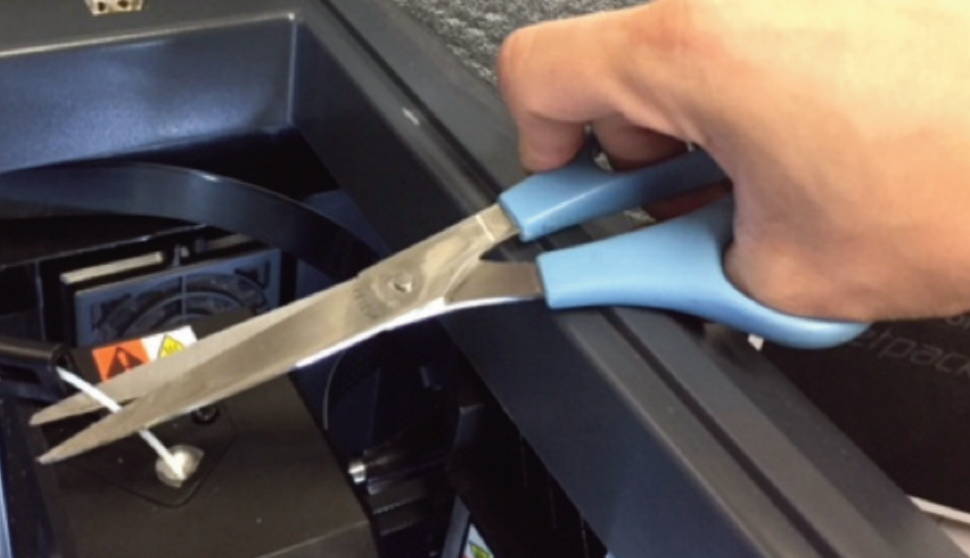
1. Cut filament.
2. Pre-heat the extruder, go to Tools/Pre-heat. Wait until the extruder temperature reaches the recommended temperature for your filament and click Purge.
3. Push down on the lever on the side of extruder to release tension on the filament, and push the filament with a light force using the unclog tool. Check for filament extruding.
Replacing Runout Sensor on the 3D40-FLX
In this page you will find the steps to replace the filament run-out sensor, follow the steps.
Tools Required
• T10 Torx bit or screwdriver (no longer than 4 inches).
Instructions

a. Cut the filament just before the intake on the top of the extruder.
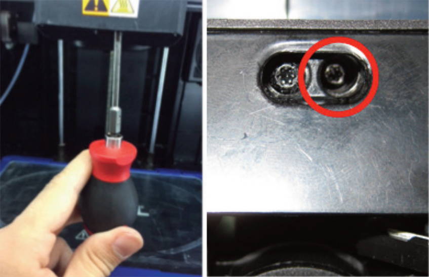
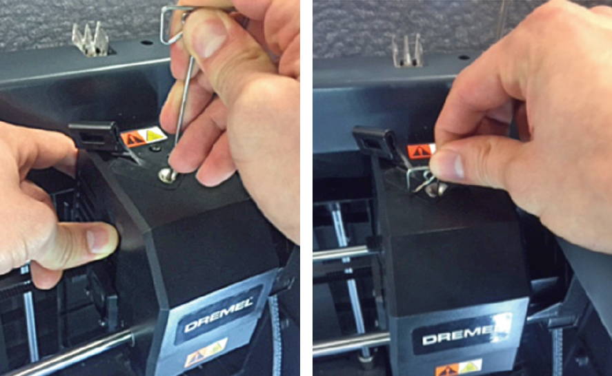
b. Remove screw located on the right side of the hole using the T10 Torx screwdriver. The first picture above shows the location of the screw, the second picture a bottom view of the area where the screw is located, circled in red is the screw that needs to be removed.
c. Unscrew the two screws on the top of the filament guide bracket usingthe 2.5mm bit or Hex wrench.
d. Remove the top cover.
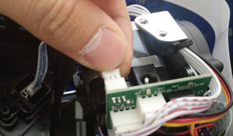
e. Carefully unplug filament run out switch from the extruder circuit board, ensuring to pull from the plastic plug and not the wires; pulling the wires can damage the connection to the extruder. Please see picture above.
Nozzle Gap Calibration
If you are having first layer issues, calibrating your nozzle gap (or z-gap) could be the solution to your printing issues. If the nozzle gap is too small, you may be hearing a clicking at the beginning of your print, or you may have a first layer that appears "smashed" or too flat. If your nozzle gap is too large, your first layer may print in air, or just have poor bed adhesion. If you have 1st layer issues multiple prints in a row, try following these directions to calibrate your nozzle gap.
Instructions
Step 1: Test the machine
a)Level the printer before moving forward – Navigate to the leveling screen by pressing level on the home screen, and following the instructions on screen.
b) Navigate to “Filament” and follow the on screen instructions to load filament.
c) Build the “Test Print” file on the machine to ensure the 3D40 printer is working correctly.
d) If prints are not adhering to the build plate, the z-axis offset may need to be adjusted. If so, continue to step 2.
Step 2: Adjusting the z-axis offset
a) Navigate to the z-axis offset screen, following: Tools→ Settings→ Z-Axis Offset.
b) Follow the on-screen instructions to either increase or decrease the offset.
c) Always adjust the z axis offset once (0.1mm increments/ decrements) and test by repeating Step 1 above, before making any further z axis offset adjustments.